
Fire Alarm, Security and CCTV Cable: An Overview
Security and alarm cables are among the most overlooked cables we sell here at CableWholesale. Unlike audio/visual or networking cables, most fire alarm wiring technology has not changed in decades even with advances in alarm systems and their associated detection devices. This being said, the wiring that goes into an alarm system is as critical as any wire can be. Fire and security alarm cable provides the basic framework upon which all of a building's asset protection is based.
“ Fire and security alarm cable provides the basic framework upon which all of a building's asset protection is based ”
Basic Fire Alarm Systems
Most fire alarm systems fall into two categories: conventional or addressable. Conventional fire alarm systems are a simple, common, time-proven technology, which protect a large percentage of commercial buildings today. Their reliability and low cost make them ideal for small to medium size properties. Conventional fire alarm systems are characterized by a fire alarm control panel, which holds the entire system's intelligence. Connected to this panel via hard wires are a number of detectors or initiating devices such as smoke, flame or heat detectors. Additionally, the control panel is wired to notification devices such alarm bells, strobe lights and automatic dialers.
Addressable (intelligent) systems assign a unique address to each connected initiating device such as smoke and heat detectors or pull switches. This design makes for easy troubleshooting and servicing the system since a technician can isolate faulty devices. Addressable systems also require less cabling than conventional systems since all devices can be placed on a single loop of cable running through the premises.
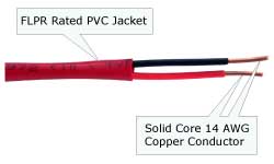 16/2 FLPR Rated Fire Alarm Cable |
Smoke Detectors and Fire Wire
Unlike the small stand-alone smoke detectors found in homes, units for commercial usage are typically hard wired. These AC powered devices are wired together to act as an integrated system so that if one smoke detector goes off, all the others will follow suit. A common fire alarm wiring pattern for smoke detectors is to run a 2-conductor cable, such as 14/2, from the breaker panel to first smoke detector and then 3-conductor cable from each detector to another onward. The third wire is for tripping all of the detectors should one detect smoke.
Fire alarm cable, just like networking cables, comes in either shielded or unshielded varieties. Shielded fire wire is usually needed only for noisy EMI (ElectroMagnetic Interference) environments or for extremely long runs. One should note that excessive capacitance becomes an issue here two especially in addressable systems. In shielded fire cable, a capacitor is formed not only between the conductors, but also between each conductor and the shield. While the capacitance values are typically around 30 to 75 pF per foot for each of the two previously listed capacitors, this value adds up quickly to the low hundred μFs with cables runs in thousands of feet.
Another distinguishing detail between different fire wire is the number of conductors. Fire alarm cable is available with two to six conductors, all of which are normally rated for up to 300 VRMS. The number of conductors required is dependent upon the type of system (conventional, addressable or hybrid) and the device type.
Which AWG Do You Need?
| Wire Gauge | Conductor Diameter | Resistance | Loop Resistance |
|---|---|---|---|
| 18 AWG | 0.0403" | 6.5 Ω/1,000 ft | 13.0 Ω/1,000 ft loop |
| 16 AWG | 0.0508" | 4.1 Ω/1,000 ft | 8.2 Ω/1,000 ft loop |
| 14 AWG | 0.0641" | 2.6 Ω/1,000 ft | 5.2 Ω/1,000 ft loop |
| 12 AWG | 0.0808" | 1.8 Ω/1,000 ft | 3.6 Ω/1,000 ft loop |
| Typical Fire Cable Solid Core Wire Resistance | |||
This can be a little confusing as fire alarm cable ranges in size from 18 AWG up to 12 AWG (American Wire Gauge; the smaller the value, the larger the wire diameter). The size of the wire required for the job is dependent upon each individual detector or notification device within the circuit receiving sufficient voltage to operate. This is due to the wire itself causing a voltage drop to its own internal resistance. The larger the wire gauge, the less resistance and associated voltage drop.
| Using 18 AWG Wire: |
 |
| Using 14 AWG Wire: |
 |
Let's consider a system where the devices are connected in series. Just like the wire, each detector is going to exhibit its own voltage drop. For this example, we are going to combine all but the last device into one to make sure that the last unit in the chain receives enough voltage to operate. Let's say we have 30 smoke detectors, each requiring 35 mA of current. These units have a minimum voltage of 8.5 VDC, a maximum of 30 VDC and a nominal voltage of 12 VDC. Our system power supply outputs 18 VDC. Connecting the system with 18 gauge wire will cause the following voltage drop: 29 devices (All but the last one) x 35 mA (current per device) x 3,000 feet (assume all the wire is in front of the last detector) x 6.5 ohms (resistance per 1,000 feet of wire) = 19.8 V. This means that the last device will have -1.8 V to operate with which obviously will not work. Applying the same calculation with the 16 AWG wire yields 5.5 V for the last detector which is still below the minimum required voltage of 8.5 V so this wire gauge also has too much resistance because of its small size. Using 14 AWG wire however, provides much better results. As can be seen in the calculations to the left, 14 AWG wire allows for at least 10.1 V for the last device which will work for our application.
Security Cable
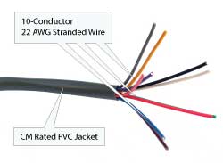 22/10 (22AWG 10C) Stranded CM Security Cable |
Security cable, also known as alarm wire, typically comes in a sheath, which covers two or four wires. The number of conductors is dependent upon the type of sensor being connected to the system. Simple devices such as window and door sensors are passive make/break elements and do not need an external supply of power. As a result, they only require a 4-conductor wire for installation (two wires for the device and two more for the 24-hour tamper loop). More sophisticated devices such as motion detectors are active and require 6-conductor wire (two wires for the detection circuit, two wires for the 24-hour tamper loop and two for connecting to the external power supply). The control panel, being the most sophisticated component of a burglar alarm, requires anywhere from 6 to 10-conductor security cable with 6-conductor being the most common.
Wire gauge is a consideration for security alarm wire too. Most security alarm devices run on lower voltages than fire alarm systems and thus do not require such large wire gauges as the latter. For most sensors, 22 AWG is the nominal gauge due to their extremely low current draws. The other most common security wire gauge is 18 AWG, which is used for higher power consumption devices like sirens or transformers.
CCTV Cable
RG-59 Siamese CCTV Cable
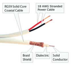 RG59 Siamese Solid Coaxial Cable + 18/2 |
“It should be noted that not all RG-59 cables have the same specs.”
Most wired CCTV (Closed Circuit TeleVision) systems are connected with RG-59 Siamese cable. This integrated cable comprises of two individual cables conveniently run side by side for transferring both video and power signals within the same package. The power section of the cable comprises of two 18 AWG stranded copper wires for running either AC or DC voltage to the cameras from either a transformer or a CCTV power supply. These wires are typically rated for up to 30 V. The most common method for connecting the power cable to the camera is with a 2.1mm power pigtail type connector.
The video signal is sent via the solid core coaxial RG-59. The name refers to the "59th" page of an obsolete military specification "Radio Guide". It should be noted that not all RG-59 cables have the same specs. Generally, they will all have solid core center conductors, shielding and an impedance of 75 ohms. [Factoid: the 75 ohms refers to the nominal impedance of a half-wave dipole antenna.] For optimal video signal transfer, RG-59 cable should have a 20 AWG solid copper conductor with a AL-Mylar foil shield in addition to a 95% coverage pure copper braid shield. Some RG-59 cable is sold with a 22 AWG solid core copper clad steel conductor surrounded by Al-poly foil and 60% coverage Al braid shield.
For the video connection, nearly all CCTVs are connected with BNC (Bayonet Neill-Concelman) type connectors. BNCs are weather resistant, twist-locking, coaxial connectors that are also deployed in most professional video cabling applications. These connectors provide a secure physical connection between the cable and component with less than 180-degree rotation.